
In a grid-connected inverter, a filter is the interface between the inverter and the power grid. According to the IEEE 519- STD, grid current harmonic order higher than 35 times the fundamental frequency must be less than 0.3% and the total harmonic distortion (THD) should be lower than 5%. Unipolar SPWM is used for inverter switching, shifting harmonics to sidebands around twice the switching frequency, which the LCL filter is specifically tuned to attenuate. The inverter side inductor L₁ is sized based on two key constraints: the ripple current and the fundamental voltage drop. Its minimum value is dictated by limiting peak to peak ripple to around 30% of rated current, a typical boundary in inverter side inductor design to keep switching losses manageable and the filter effective. Meanwhile, the maximum value of L₁ is constrained by the voltage drop it introduces usually capped at around 5% of the grid voltage - to ensure that the fundamental component is delivered without significant attenuation. In light of these design criteria, an inverter side inductance of 12 mH was selected for an inverter rated at 1.27 kV and 13.33 kVA. The filter capacitor C is designed based on the reactive power introduced by the filter capacitor to the rated output active power of the grid-connected inverter. The ratio of reactive power introduced by the filter capacitor to the rated output active power of the grid-connected inverter is considered to be 4%. The value of the filter capacitor chosen is 1uF. After the inverter-side inductor and the filter capacitor are designed, the grid-side inductor L2 is designed according to the IEEE harmonic restriction standards. The harmonic proportion for the grid side inductor is considered to be 3% and value of grid-side inductor is 4 mH. The inductor core is chosen such that the core loss will be minimum and efficiency will be maximum. Amorphous Core has a non- crystalline atomic structure and a higher saturation flux density compared to a ferrite core. The thickness of the amorphous metal sheet is 0.025 mm, which results in lower eddy current losses as compared to a laminated iron core. Hence, the inductor is designed using an amorphous core. This work was done by NCPRE student, Rajvardhan Patil, under the guidance of Prof B.G. Fernandes and Prof.
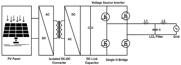
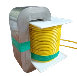
(L) Grid Connected Inverter with LCL Filter, (R) Amorphous Inductor.