
An integrated magnetic design approach is studied for design of a line-frequency zig-zag transformer, which is employed in a unified ac-dc (UACDC) system to integrate low voltage solar photovoltaics (PV) with three-phase ac grid. It is deduced that in case of the UACDC system, the interleaved winding strategy is the best suited for the zig-zag transformer design, where the primary (high-voltage) winding is placed between the zig and zag (low-voltage) winding sections. Benefits of interleaving are two-fold i.e. (a) It improves the integrated boost inductance, offered by zig-zag winding sections, which is beneficial for interfacing the low voltage PV with the common dc bus of the PWM converter. (b) It also keeps the eddy current effect minimal in the multi-layer winding sections, thereby reducing the copper loss and improving the transformer efficiency. To verify the effects of winding arrangements on the design performances of the zig-zag transformer, two winding systems are studied i.e. (a) normal winding, where the zig-zag (low-voltage) windings are placed near to the core and the primary (high-voltage) winding is placed outside. (b) interleaved winding, where the primary (high-voltage) winding is placed in between zig-zag (low-voltage) winding sections.
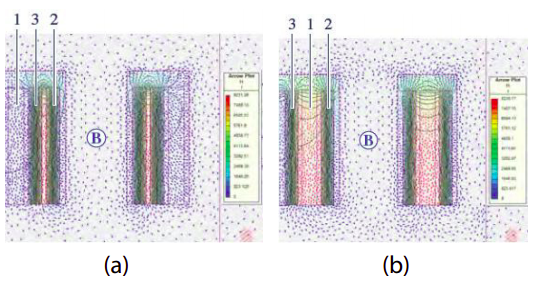
Figure : 2-D FEM results results show the effect of winding arrangements on the magnetic field intensity (H), when excited from the PV source. (a) In the normal winding,H(x) attains a maximum value of +8.14 A/mm but is confined in the zigzag windings only. (b) In the interleaved winding, H(x) attains a maximum value of +8.13 A/mm but the entire primary winding acts as an additional leakage layer, culminating into higher stored leakage energy. It thereby achieves a high value of integrated boost inductance(Lpv), offered by the zig-zag winding sections.
In the figure above 2-D finite element method (FEM) analysis shows that in case of the interleaved winding arrangement, the integrated boost inductance for zig-zag winding sections is significantly enhanced, which is beneficial to interface the low voltage photovoltaic (PV) with the high voltage dc bus of the PWM converter and keep current ripple within desired limits. Interleaving winding arrangement also keeps the proximity effect minimal in the multi-layer winding sections of zig-zag transformer; as the winding ac resistances are kept low, it reduces the fundamental and harmonic copper losses in the transformer windings and improves its efficiency. To corroborate these findings, an experimental prototype of a 1kW, 415/130 V, 50 Hz, zig-zag transformer is built and tested. The winding ac resistances of the zig-zag transformer are measured over a wide frequency range with the help of a programmable LCR bridge as shown in the figure below . The predicted and measured values agree well, indicating a good modelling accuracy and verifies the aiding effect of interleaving to minimize the ac effect in multi-layer winding sections.
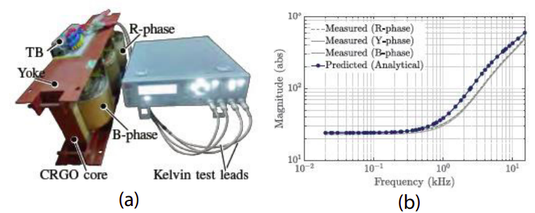
Figure : (a) Winding ac resistances of zig-zag transformer are measured between the frequency ranges of 20 Hz and 15 kHz using a programmable LCR bridg (HM8118). (b) Predicted and measured values of the winding ac resistances agree well indicating a good modelling accuracy.