
The solar electricity action works on the principle of the Photovoltaic effect. As we go deep into the photon level, we define Quantum Efficiency (QE) of a cell at a given wavelength as the short circuit current per incident photon from the solar cell. Ideally, each photon absorbed by a solar cell can produce a current flow of one electron if the terminals of the solar cell are shorted, which leads to 100% QE. Depending on the total number of photons absorbed by the solar cell, one gets the maximum current that a solar cell can produce under short circuit condition. In the case of real solar cells, the short circuit current is less than its maximum. That is because QE is less than 100% for photons of different wavelengths of the solar spectrum and depends on the cell design, material etc. For a single cell, the QE measurement is straightiorward as per equation below:
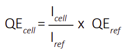
where Icell and Iref are the short circuit currents of the solar cell (Icell) and reference solar cell (Iref) (whose QE is known) at a particular wavelength. However, in a solar module, many cells are connected in series. Non-availability of direct access to a cell in the module makes it not an easy process to extract the QE of that cell.
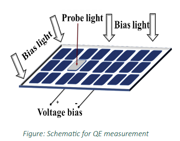
So, the challenge is how to measure the QE of a selected cell in a module without having access to theindividual solar cell terminals. It turns out that it is still possible to measure the QE of a selected cell if the test cell controls the current flow through the module terminals. This is done by illuminating the whole module with a white bias light except the test cell which is illuminated with a fraction of the same white light (by shading) as shown in the figure.
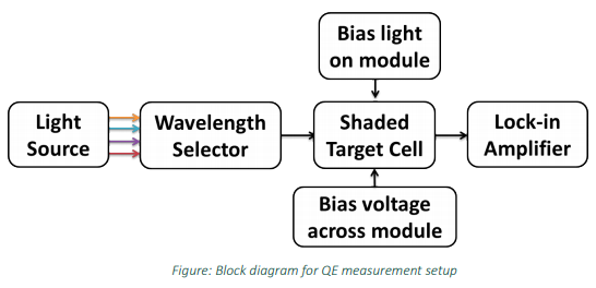
Prototype- The technique employs LEDs with around 20 different wavelengths ranging from 300nm - 1100nm. The use of LEDs would eliminate the need for monochromator to help in making the system more robust by reducing the mechanical parts. The novel, custom 3-D printed LED holders were designed in IIT Bombay, and Fibre Optic cables were used to reduce coupling loss. The above-mentioned principle incorporated while developing the prototype as shown in the block diagram of the setup.
The prototype developed was tested for QE measurement of a cell in mini-modules and
has shown fruitiul
results. This was further extended to understand the modifications required in the
prototype for
commercial modules (6-inch solar cell). Usually, a commercial module has additional
components such as
bypass diodes across a string of solar cells for protection against partial shading.
This bypasses the test cell
string making it difficult to measure the QE of the test cell. In order to verify if
the method followed for
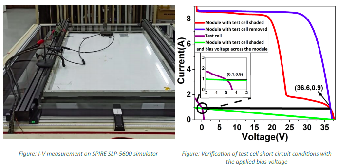
mini-modules is valid for commercial modules with bypass diodes, we considered a 72
cell module. It has
three bypass diodes for a string of 24 cells. The electrical terminals of the test
cell were extracted from the
backsheet and the I-V for the module and the test cell were measured on SPIRE
SLP-5600 simulator as
shown in the figure.
The short circuit condition of the test cell was observed by calculating and
applying the required bias
voltage across the module. The results proved that the bypass diodes didn’t affect
the test cell current
limiting condition. Also, the applied bias voltage –36.6 V (blue and red curve
intersection point) maintains
the test cell at nearly short circuit condition i.e., 100 mV (green and violet curve
intersection) as shown in
the graph for voltage bias calculation.